I learned
something new about Teflon tape this past weekend......and
learned I was wrong two years later......so keep on
reading!!
Now, I've known that you shouldn't use the basic
plumbing Teflon tape in a gas environment but what I
didn't know is that there are different Teflon tapes
for use in different conditions
|
Blue, Yellow &
Red Teflon Tapes |
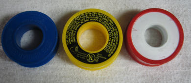 |
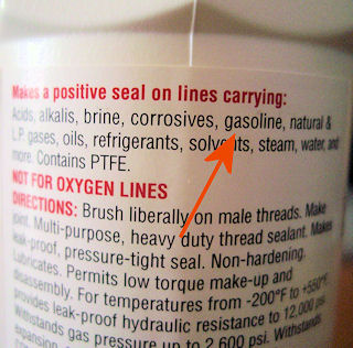
The tape
that's in the blue package is for regular plumbing
in a water environment. The red is for use with
solvents while the yellow is for use with gas............as
in natural gas.........but I thought gas meant
gasoline and used the yellow tape on all my gasoline
fittings. So now (12/2008) I've learned that I used
the wrong stuff and I'll be changing every gas
fitting out and using the correct product for a
gasoline environment.
|
Available at your
local Home Depot Plumbing Department.......
a life time supply! |
 |
 |
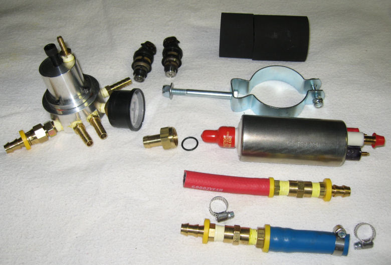
John sent me all the parts required for
getting the fuel from the tank to the carbs/TBI. The
electronics and my converted/modified distributor
should arrive around Christmas.
|
Regulator, 2
injectors, Fuel Pump, Pump Sleeve & Bracket
with Hoses and Fittings
The fittings with the yellow rings are Push
Lock fittings with no camps required.
But look at all the yellow Teflon tape that
has to be replaced!! |
 |
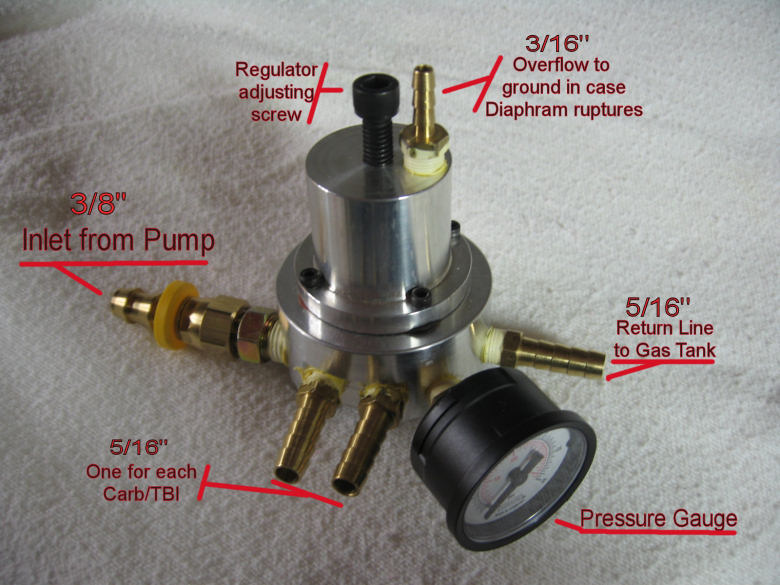
The
regulator is custom made from billeted aluminum for
these conversions and has a number of fittings
better seen in the picture below.
|
Looks like a
pretty complete regulator to me - The return
line is needed because about 50% of the fuel
delivered isn't needed, so it gets returned
to the gas tank! |
 |
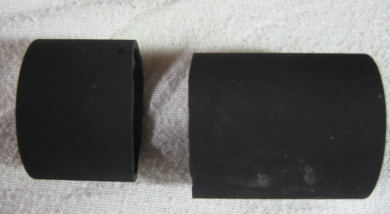
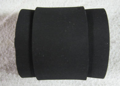
There's a
rubber sleeve that comes with the pump which needs
to be cut so that you have a 1/3 piece and a 2/3's
piece. Then the big piece goes in the little piece
and the whole thing slides over the pump. Rub a
little liquid soap over the pump housing and it will
slide right on.
|
Cut 1/3 off and then slide the big part into
the little part |
The Double Sleeve goes over the pump with a
little soap |
 |
 |
|
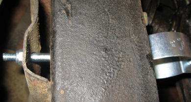
Pump in Mounting
Bracket - Included bolt was to short too
mount to TR6 frame |
|
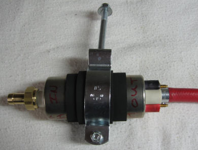 |
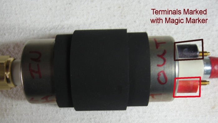
The next
picture shows the sleeve on the pump but more
importantly, it shows the terminals have been
"painted" with magic marker and the In and Out sides
of the pump have also been marked. The reason for
doing this is to make sure there's no mistake made
when you're attaching the pump to the frame. The
terminal + & - marks are stamped on the pump but
they're very hard to see. So use a red marker on the
+ terminal and a black marker on the - terminal.
|
Marking the
Terminals Saves Aggravation |
 |
|
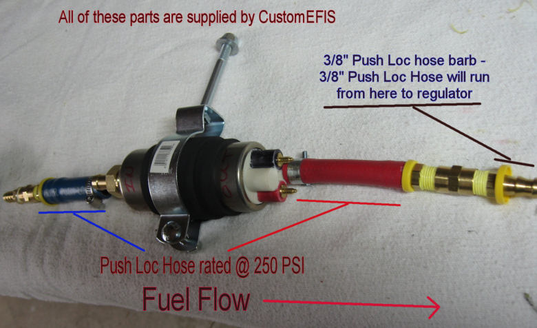
Now the Fuel Pump
Parts - All supplied by John |
 |
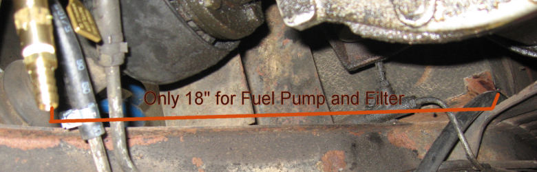
Once I
got to actually putting this pump assembly up under
the car, I realized we had a problem.........I had
18" of room in which to fit over 20" of pump,
fittings and filter. I'm not great at math but I
knew this wasn't going to work. I exchanged a few
emails with both Rick and John and Rick
emailed me NAPA part numbers for fittings that would
eliminate the Blue and Red hoses that John provides.
John provides this set up for all of his
applications which tend to be more American Iron
then LBC so there's more frame space available. As
noted on the previous page, the filter is now
mounted vertically which freed up even more space.
|
Fuel Pump and
Fittings Need to Fit Here |
 |
|
This Got The Pump
& Fittings Down To 12 1/2" |
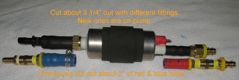 |
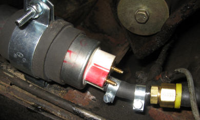
This is
the final configuration of fittings for the pump.
With Rick Patton's help, he came up with NAPA part
numbers that allowed for a minimum of pieces to get
to the correct hose size. On the left, the pump has
a 1/2" barb that has to get reduced to a 3/8" barb
to match the hose from the tank. On the right the
pump has a 5/16" barb has has to get increased to
3/8" to match the hose going to the carbs. Obviously
I haven't put any clamps on the hose yet in this
picture. And now a word about Push-Loc
fittings..........they are a PAIN to work with but
here's a few tips to make it easier:
-
Give
yourself "elbow" room and extra hose to work
with. I did the pump end before running the hose
along the chassis.
-
Slop
lots of ATF (automatic transmission fluid) on
the barb for lubrication.
-
Use a
Q-Tip and coat the inside of the hose end with
ATF.
-
Warm
up the hose end. I used a heat gun to warm the
last 4 inches of hose to make it more pliable. I
heated it to the point where it was quite warm
to the touch. This was critical when working in
50 degree weather. Maybe if it was 90 out it
wouldn't be an issue.
-
Line
the hose and barb up and push with all your
might! You want to get the hose up against the
yellow plastic collar.
-
Run
the hose along the chassis all the way to where
the regulator will mount and tie it loosely in
place. Cut it to length and then cut the wire
ties to give you needed slack at the
regulator end. Now repeat the steps above.
-
There
are no clamps used with Push-Loc fittings....the
fittings with the yellow plastic ring.
|
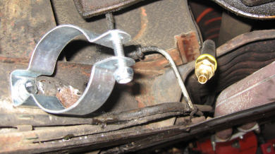
Fuel Pump Bracket
Mounted to Frame |
Required a 4"
long 5/16" Bolt |
 |
 |
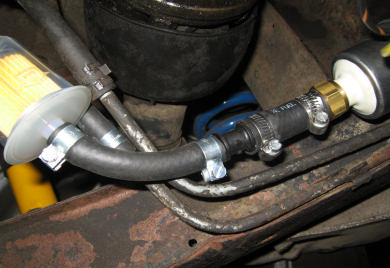
|
Filter to Pump
Input |
Pump Output to
Fuel Line |
 |
 |
Next Up
is Running the Fuel Lines....more